1.) New type of ship propulsion 1a) The shovel band 1b) Constant efficiency 1c) Enclosure shovel belt 2.) Turbulence = basics 2a) Energy wasted by turbulence 3.) Turning in standing position 4.) Experiments at a shipbuilding research institute 5.) Technical details 5a) Elimination of the shallow water problem 6.) Efficiency and added value 7) From the energy savings at …. 8.) Market potential 9.) Credits 10.) Imprint
The 10 advantages of the NEW SHIP DRIVE
- Fuel savings of up to 40% by eliminating turbulence.
- Savings of another approx. 25% by creating a laminar flow.
- Consistently high thrust even at low water.
- No damage to fauna and flora on the ground due to water turbulence.
- Cargo reduction no longer required at low tide.
- New ship drive can be retrofitted without hull – change.
- Existing motors (machines) are used for retrofitting.
- A retrofit already pays for itself after approx. 2 years.
- Maneuverability = Turn 360 degrees while standing in position.
- Government investment grant can be granted.
A ship’s propeller drive creates turbulence with a high fuel consumption – . The new ship drive produces a laminar flow instead of turbulence – with the well-known fuel savings of up to 40% – depending on the journey. Another innovation: The new technology turns the ship standing on its position by 360 degrees.
1a) The blade band length and the sum of the areas are designed according to the required ship performance. The existing engines are used for ship retrofits. The technology therefore consists only of the BAND construction and the associated mechanics. An investment that pays for itself in about 2 years. Plus government subsidy and approx. 40% fuel savings.
1 b) Consistent efficiency even at low water: Here, too, the blades of the belt still grip the entire surface. The gray area is the ship’s outer wall to port (port). The shovels can be put back to the bow when they are transported and automatically brought into the thrust position before they are immersed again
1 c) The shovel band – efficiency is increased by the boxing (video on the right). Further advantages: a) avoiding process water loss b) preventing grounding c) wave and flotsam deflection – takes place at the front through aerodynamically optimized baffles.
It is not only for reasons of energy saving that the ship’s propeller drive should be substituted. The environmental damage caused by turbulence in inland waters is significant.
The aim of the rotation of a ship’s propeller is to propel a ship forward by generating water movement. However, this water movement can only take place at the acceptance of water turbulences, which are not involved in the objective of ship propulsion. With increasing speed, the proportion of turbulence increases and the power of the ship’s propulsion system decreases as a percentage. As a result, the fuel costs, which are permanently used for this – must. The fact is: The ship’s propeller drive cannot be rehabilitated in terms of eliminating the turbulence it generates itself. A scientific report states the following regarding the urgency of ending environmental damage caused by ship propellers – impacts on inland waters: „…it is high time that this urgency was recognized everywhere.“ What has happened – and is happening continuously below the waterline in our inland waters? Without it being apparent to the general public? The generated water turbulence kills the fish spawn. Plant life is also destroyed. This clear-cutting takes place in some waters daily, depending on shipping traffic. A recovery of these conditions is therefore impossible. Depending on the ground conditions, there is also silting up of the This problem can be permanently eliminated by using the new, laminar ship drive, in addition to the significant savings in fuel costs for inland shipping
2 a) Visible, process-related energy waste in ship propulsion systems.


Turbulent stern wave push ship or tug
Turbulent stern wave yacht or inland freighter
Comparison of Forces:
Turbulent / Lamina
Comparison: Old and new drive technology:


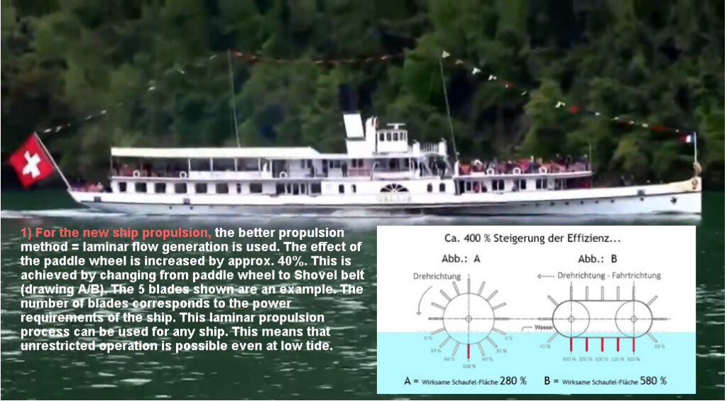
To 2: RED shows the water movement; generated with a ship’s propeller. The laminar water flow that is optimal for propelling the ship is only approximately produced in zone 60%. In the edge zones, hardly any propulsion is produced. The alternative is: The laminar flow (= GREEN ) Several of the blades are in function on both sides of the ship; whose total area has the required effective area.
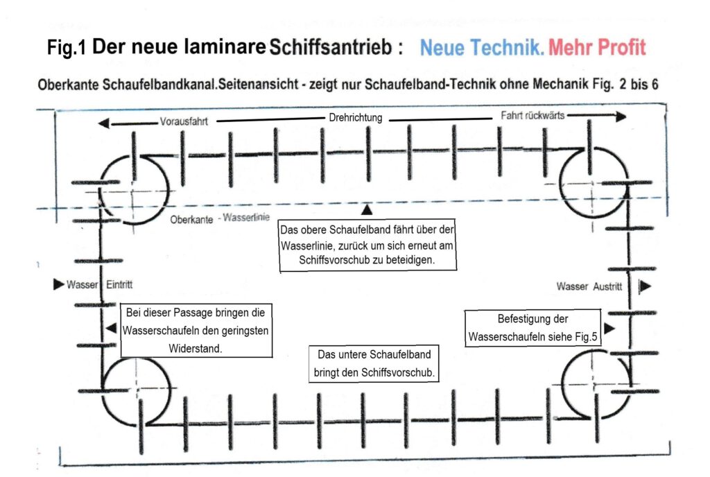
The laminar blade conveyor drive (DPMA). The blade belt produces the feed, runs in a square channel, with an opening at the front and at the end (water inlet and outlet). A carbon grating is provided at the top so that the water level in the square channel can change spontaneously. The vertical axis distance is adapted to the operational requirements of the respective ship.
New technic Example: 34 water shovels, each with an area of 0.64 m², 11 of which provide thrust in the water. Total: 1x each on starboard and 1x on port = 14.08 m². Construction length approx. 10 m. This area can be increased without changing the main dimensions of the technology. See Fig. 2 to Fig. 6 and installation note DPMA
More profit Draft 1.80 m = higher freight possible at low tide according to the weight of the 50% amount of fuel saving. The overall economic efficiency of the ship increases by around 70%. The state pays a subsidy of up to 80% for your investment = free money. I’m helping them with this fundraising.

3) Turning a ship while standing on its position.
The red VIDEO shows a catamaran hull. This design is not mandatory for the new process. Retrofits of the new process on existing ships – with the same effectiveness as on new builds – are made on the STB and PORT of the ship.
The tacking manoeuvre: The wind influences the change in position of a ship in open water by putting the ship in its wind direction. This influence depends on the wind force and the size and position of the structures on deck (= wind resistance). The animation shows superstructures of a certain height located about halfway down the aft deck. The shovel belt is designed according to this position and length and is effective on both sides of the ship. The most favorable position for this paddle belt drive is thus selected in order to have a balancing effect on a wind (offshore or onshore) acting on the broadside of the ship. In addition, bow thrusters should be installed at the bow, so that the ship can make a perfect turn (tack) in its standing position – unhindered – at any wind strength.
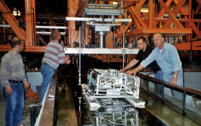
4) Before realizing a technical idea, it is advantageous to consult results from technical tests in a shipbuilding research institute.
For this NOVEL SHIP DRIVE project, there should be a work plan for the empirical determination of all relevant operating data. These tests are carried out in an open body of water. The objective is primarily to develop empirical operating data for the needs of the ship type in question, which represents the largest market share for the application of this laminar process. Within this group, individual performance parameters are to be defined: The aim should be to create the most extensive standardization of the technology possible, as suggested by the respective parameters. Potential buyers/investors should be on board during these test drives. Such measures have proven to be an efficient acquisition measure in similar projects in the past.
5) The new technology – for retrofitting and new ships.
The extensive explanations in words, pictures, videos and comments on the WEBSITE can be summarized as follows: This new technology has the advantage that it can be adapted to existing ship constructions without having to change their structure . Unless it is an advantage, because the higher processing power of the laminar drive requires a lower machine power. In addition, slow-moving vehicles can be used for new buildings.
a) When converting existing ships, the existing, already installed engines are used. The engine power is transmitted to the two shafts of the two transport roller pairs (on port and starboard) via reduction gears. The motor supplier should determine whether it makes sense to reduce the speed of the motors. If that doesn’t bring any advantages, gear reductions should be installed. The required speed of the shovel belt transport rollers is only a fraction of the speed of the mounted ship engines.
b) For tugs and push boats; instead of retrofitting new buildings. These ships have a small overall length, which will not be sufficient for the required length of the shovel belt. Example: See point 6 = 2×1700 KW. With an achievable saving of approx. 40% of the consumption and an accepted amortization period of 4 years, an investment amount (new construction) for such a ship type of around €1.2 million results. Added to this is the advantage of a government subsidy. These are certainly interesting perspectives for the shipowners and shipyards in question. In this context, it should also be considered that value is added with the higher profitability of the converted (also new) ship. The resulting higher value of the ship – which now has a higher intrinsic value – enables a bank to rate the future lending value of the ship higher. In addition, the elimination of the risk of decommissioning (operational restrictions) of the ship due to the annual low water in the inland waters is positively evaluated in this context.
c) Wave and flotsam deflection: After enclosing the two paddle belts (on starboard and port) with their drive technology, a plough-like water deflector is attached to the bow of the respective paddle belt box (= channel) for the purpose of deflecting high waves and Flotsam. By enclosing the blade belt constructions, a higher thrust (= ship propulsion) is achieved, since a loss of the working medium water is largely avoided.
d) The structural scope of the boxing with mechanics: This is led to the upper edge of the deck and covered over its entire length with a grating made of lightweight material (carbon). The railing should be mounted on the enclosing on the seaward side, provided that it conforms to the building regulations. The function of the rubbing strake on the ship is attached to the outside of the box in a stable tubular construction. This acts with its load transfer to the existing rubbing strake of the ship in the event of external stress.
e) The existing (in the case of retrofits) rudder system must be used. It must function independently of the shovel belt control (= direction of rotation of the shovel belt) during the turning process. It is to be expected that this conventional rudder system will not be required when the wind is steady, but that it will have to help with the turning process of the ship in winds of 4 to 5 Bft. However, these higher wind speeds are only to be expected in the waters around the seaports. Since these are also approached by inland vessels for the purpose of transferring cargo to overseas ships, appropriate technical precautions should be taken.
f) Low water will no longer be a problem in the future: In contrast to the propeller drive, the laminar system is not dependent on a water depth of more than approx. 40 cm from the lower edge of the water blade to the bottom, since water – as a process medium – is offered to this drive. A ship’s propeller has to suck in the process medium water and is increasingly hindered by the hull of the ship when the water is low. This significantly reduces the ship’s propulsion. This is one of several reasons why significantly fewer goods can be transported on the Rhine and Elbe – for example – with the annual low water. This reduces the profitability of the inland vessels concerned. In addition, the environment is increasingly being polluted.
g) The scoop band; assembly and function. Here is shown an inland freighter of about 80 m length going downhill. To be recognized by the non-seaman by the low bow wave and the high freeboard, i.e. the high proportion of the hull protruding above the water. Fuel consumption and future savings: An inland freighter of this type and size consumes approx. 400 liters / h of diesel on a descent; on ascents approx. 500 liters / h diesel. About 3 tons of diesel are bunkered as a reserve. About 15 to 20% of the actual consumption is used to generate the ship’s propeller turbulence; which is as good as not involved in the propulsion of the ship. See Section #2 = Turbulence. However, if the laminar drive system (bucket belt construction) is used, diesel savings of up to 45% can be achieved. The new drive technology is mounted on both sides in the rear area of the hull and is shown here openly; i.e. without the final wall on the sea side. In this way it can be seen exactly that the assembly must be carried out in such a way that the bottom row of the water scoops are still fully covered by the water and are therefore fully functional. The size of the diameter of the drive and deflection discs (white) determines the height (level) at which the upper row of blades moves back to the bow.
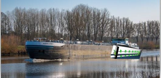

Explanation of the images above. The photomontages show one of the blade bands adapted to the ship’s hull aft – as an orientation for the viewer. In fact, the assembly of this technology is carried out with the lower part of the blade band in the water. The length of this construction shown is also not binding but is adapted to the required propulsion power of the ship.
5a) How to eliminate the shallow water problem:
The laminar propulsion system not only has the unique selling point of the highest fuel savings of ship propulsion systems. The following facts are no less important:
The laminar process works outside of the ship’s hull on port and starboard and is unhindered by them. The ship’s propeller method works directly behind the stern and must be able to work at a distance, otherwise there is a lack of water flow to the ship’s propeller. When driving aft (back) there is the problem of air being sucked in by the ship’s propeller. Therefore, the ship’s propeller needs a sufficient distance to the water level of at least half the diameter of the ship’s propeller. The distance to the bottom of the body of water should not be greater, otherwise the inflowing water cannot be fully caught by the ship’s propeller. These operational impairments do not exist with the laminar drive. Here the water flows freely and unhindered into the laminar propulsion technology in every operating phase of the ship.
Low water threatens us all, not just inland shipping.
The figures in the data table (year 2021 / 2022) of the BINNERSCHIFFER-VERBAND (Internet) show that around 195 million tons of freight are transported on the waterways -mainly- the RHEIN and ELBE each year. If, for example, 20% less freight is transported due to low water, then this 20% freight must be transported by truck. Since a truck can load 20 tons, a fleet of umpteen trucks is required for this transport service. This fleet of tens of trucks, which is on the road near the cities – partly in the cities – also pollutes the already polluted breathing air and damages us all in this way – additionally. This scenario already takes place with about 20% less cargo transport on the water. With increasing low water, everyone can see what unbearable, additional environmental pollution of our immediate living space is imminent. The associated economic slump in inland shipping is added to this. It is therefore urgently necessary to equip inland shipping with laminar propulsion technology in order to avert these unavoidable, expected conditions.
6) Economy and added value
1 . The number of commercial inland waterway vessels is 1,950 – such as tugboats, pushboats and other cargo vessels for the transport of goods (source: BINNENSCHIFFER-Verband).
2. The number of ships for passenger transport, i.e. ferries and passenger ships, is 2,000 objects (source: Association of German Inland Boatmen).
7) Various users / groups benefit from the energy savings when using the new process.
Energy savings, sales strategy. Energy savings of up to 35% are achieved by switching from the turbulence of the ship’s propeller drive to the laminar blade drive. The remaining amount of fuel required for the ship’s drive of around 70% is reduced by around 25 % due to the higher feed performance of the laminar drive system.
The sum of the savings to be achieved (35% plus 25%) brings an increase in that the cargo transport performance of the cargo ship can be increased in accordance with the amount of fuel in weight (kg). With the exception of this gain, the same fuel savings can be achieved on passenger ships.
8) Market potential / sales strategy.
In order to start a successful marketing campaign, it is necessary to at least two, better three, revenue areas to be tackled.
1) For shipyards: domestic production licenses. Also limited to application areas possible. With option for abroad (EU and USA).
2) For shipowners: license for exclusive regional use. Participation in the sale of this technology by the shipyards.
Successfully tackling the market potential through acquisition… requires at least one type of ship, regardless of the type and use, to be on the water. Once this has been achieved and prospective buyers are invited to demonstration trips, a contract of sale usually follows similar new projects. This is how it has been shown: This fact has also been shown: The faster a new technology is established on the market, the more the affected industry is willing to enter into cooperation agreements. However, if a long period of time elapses for this process before a new technology becomes established, then potential producers in the industry are more willing to compete on the market with their own development
A market – similar in size to Germany – exists in the EU: If you take Poland and the Benelux countries together. All other EU countries have a lower potential. Nevertheless, the shipyard industry can be addressed here via licensees. The US market, which offers a multiple of the German market, is of immense size. Here you should already be active at the beginning, i.e. as soon as the first ship unit is in function on the water, as far as contacting the relevant shipyards is concerned. The preceding paragraph says something about the commercial prospects in general. The technical prospects for the application of this method can be seen as follows: Large ships such as CONTAINER SHIPS can achieve significant savings in operating costs when using this method. Regarding the required seaworthiness of this laminar process, the following can be said in this context: Seaworthiness is easier to achieve where large ship units – such as container ships – are to be equipped: the larger the ship in terms of dimensions and tonnage, the lower the adverse effects of rough seas (= sea weather) for the ship
9 ) References:
Association of inland shipping, Rhenus-Spedition, Kroline Messtechnik ships, Voit-Schneider drive, German-Polish Chamber of Industry and Commerce, German Consulate USA, Internet = inland shipping, Internet = development center for ship technology e.V. – Duisburg. Internet: www.ccr-ZKR.org, www.Klausiwan.de, www.Schwebe-yacht.de
10 ) Imprint: see content (Inhalt)